


- Qinsun Instruments Co., Ltd.
- Tell:+86-21-6780 0179
- Phone:+86-17740808215
- Address:No. 2578 Minhang District Gu Dai Road, Shanghai
- Contact:Mr. Li
- QQ:846490659
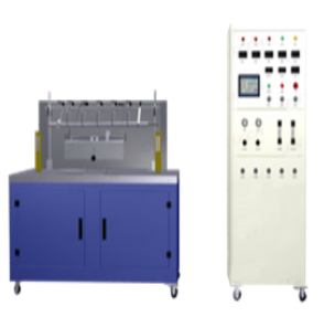
Fire resistance and combustion tester for wires and cables
Product Introduction:
Fire resistant cables refer to cables that can maintain safe operation for a certain period of time under flame combustion conditions. The fire resistance test device for wires and cables is designed in accordance with the requirements of GB/T19216.11-2003 (replacing GB12666.6) and IEC60331-11, and is used to obtain and determine the fire resistance characteristic parameters of fire-resistant cables or optical cables under flame conditions.
Applicable scope:
The Chinese national standard GB12666.6 (equivalent to IEC331) divides fire resistance testing into two levels: A and B. The A-level flame temperature is 950-1000 ℃ with a continuous fire supply time of 90 minutes, while the B-level flame temperature is 750-800 ℃ with a continuous fire supply time of 90 minutes. Throughout the entire test period, the sample should withstand the rated electrical pressure value specified by the product. This fire resistance and flammability tester can be used to test the flame resistance performance of cables or optical cables, setting clear high-temperature combustion resistance indices for different levels of cable application fields.
IEC 60331 Part 11 Testing of cables and optical cables under fire conditions - Line integrity - Part 11: Test apparatus - Single column flame with a flame temperature of at least 750 ° C
IEC 60331 Part 21 Testing of cables under fire conditions - Line integrity - Part 21: Procedures and requirements - Cables with rated voltages of 0.6/1.0kV and below
GB/T 19216 Line integrity testing of cables or optical cables under flame conditions - Part 21: Test procedures and requirements for cables with rated voltages ranging from 0.6 to 1.0 kV and below
Product features:
Structural features:
All fixtures are made of stainless steel;
The burner is a belt type propane gas nozzle with a Venturi mixer, with a nozzle length of 500mm and a width of 15mm;
The combustion holes are arranged in three staggered rows, and the width of the front end of the burner is 15mm; Hole diameter: 1.32mm, hole center distance: 3.2mm;
Install a row of guide holes on each side of the nozzle plate to maintain flame combustion;
One end of the sample holder is equipped with a clamp to fix the sample, while the other end facilitates the longitudinal transfer of heat along the sample;
The cable sample is supported by two metal rings, with a length of approximately 300mm in the middle;
The inner diameter of the metal ring supporting the sample is 150mm, and the cross-sectional diameter of the ring is 10 ± 2mm;
The position of the burner nozzle shall be no less than 200mm from the bottom of the combustion chamber and no less than 300mm from the wall of the chamber;
The horizontal axis of the burner nozzle is 70 ± 10mm away from the lower end of the cable sample, and the vertical axis of the nozzle is approximately 45mm away from the vertical axis of the cable.